Caterpillar’s C7 diesel engine series was released in released in 2003, replacing the Cat 3126. Total C7 units in operations exceeding 300,000 units, and there has been growing popularity among users of this engine for repairing and rebuilding.
As such, an overview on the engine, including general information on selected engine component groups that may be involved in service repair and maintenance processes, will be helpful in making more informed decisions.
The C7 is a 7.2 L (439 cu. in.) in-line six-cylinder turbocharged engine with a 4.33” (110mm) bore and 5.0” (127mm) stroke. It came in horsepower ratings of 190 hp to 360 hp and 520 ft/lbs to 860 ft/lbs of torque.
This midrange engine is very versatile and can often be found in on-highway trucks, as well as in off-highway applications, such as loaders, skidders, excavators and motor graders and industrial and marine units.
Cylinder Head
The single cylinder head on the C7 is similar to later version Cat 3126B heads. It features three valves per cylinder (one exhaust valve and two intake valves) and electronically-actuated injectors located between the three valves. A common push rod and rocker arm design operates the valves, driven from a camshaft located in the cylinder block.
The cross flow design head has the intake ports located on the left side. The exhaust ports are on the right.
Cylinder Block
The cylinder block features “parent” bore cylinders (i.e., it does not have replaceable liners). The cylinders can be sleeved if necessary, but be sure and follow Caterpillar’s guidelines to ensure that the block is salvageable before boring the cylinder block to accept repair sleeves.
One particular guideline explains that the cylinder block should be measured with a digital disc brake caliper to determine if the cylinder wall thickness is thick enough to accept a cylinder repair sleeve. Insert the thinner leg of the caliper approximately 1.25” into the water passage at the front between each cylinder. The block must be a minimum of 0.170” (4.3mm) for the block to be salvageable.
The use of a stress plate is also recommended for measuring and honing the cylinder diameters. For more information on stress plate usage, IPD has prepared a technical presentation to help explain the importance of this process.
Visit www.ipdparts.com, go to the IPD Section Links and then to the Technical Series Presentations section. View the Using Stress Plates to Control Cylinder Bore Distortion presentation.
Pistons
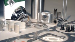
Various piston part numbers are used in Cat’s C7 engines. However, two designs are notably different. C7 engines may have aluminum or steel one-piece pistons, depending on the application.
The aluminum piston, available in the market for the longest period of time, features special coatings to improve performance.
The newer design steel piston is produced by inertia/friction welding a steel crown to a steel piston skirt, creating a piston with an internal oil cooling gallery in the crown and increased structural strength and resistance to fatigue.
A patent-pending IPDSteel welded piston design in currently in development. It is planned for release later this year.
Gear Train
The camshaft, oil pump, accessory drives and the high-pressure fuel pump for the common rail fuel system are driven by the front gear train.
Fuel System
The C7’s common rail fuel system operates under extreme pressure. The transfer pump that draws fuel from the fuel tank and supplies the fuel pump produces 280 psi (+/- 15 psi).
The high-pressure fuel pump delivers fuel to the fuel rail at approximately 27,500 psi and supplies the hydraulic electronic injectors.
Summary
The C7 engine is an important engine option powering fleets around the world.
Fleet engine service repair costs are a growing issue. This can be one area in which fleet maintenance operations can reduce costs by selecting high-quality aftermarket parts that provide savings without risk.


