In the past 15 years wheel ends have seen several significant changes. In addition to wheel ends with manually adjusted tapered roller bearings, there are now have PreSet or LMS hub assemblies and unitized hub assemblies. Along with changes to bearing types, there have been changes to seals, lubricants and spindle nut systems, all of which have brought with them new procedures for installation and service. To properly service a wheel end, it is critical that the components be accurately identified and then serviced according to the correct procedures.
To gain some insight into effective wheel end maintenance and service, Fleet Maintenance Magazine turned to Roger Maye, national service manager for Consolidated Metco (ConMet), a division of Amsted Industries. Headquartered in Vancouver, WA, ConMet is a manufacturer of lightweight components for the heavy duty transportation industry.
A recent recipient of the Technology & Maintenance Council (TMC)’s highest honor - the Silver Spark Plug Award, Maye has been with onMet since 1977, serving in a variety of positions, including quality assurance manager and performance engineer before becoming national service manager. Here is what he had to say:
In his speech at the Technology & Maintenance Council (TMC) Fall Meeting this past September, Bryan Lewis of Wal-Mart Transportation, winner of the 2007 and 2008 TMC National Technician Skills (SuperTech) competition, passed along some advice he received from a co-worker early in his career. That co-worker told Bryan that if he wanted to be a good technician he needed to learn to RTB - read the book.
For the last 6 years, I’ve had the opportunity to work with the wheel end work station at the SuperTech competition and at a good number of state and fleet technician competitions. I’ve noticed that the best contestants are the ones that make the best use the service information provided at the work station.
I now start each group with the same orientation speech. I tell the contestants that we want them to identify the task, obtain the proper work instructions and complete the task based on the work instructions. Just like Lewis learned early in his career, the service literature is the starting point for any job.
This advice could apply to each station in a skills competition, or each job a technician completes in the course of his normal work day. As a technician reads a repair order and prepares to service a vehicle, he must make a diagnosis based on information from the driver and what he sees when he inspects the vehicle. Once the diagnosis is made, he needs to obtain the service information and the parts necessary to complete the repair.
Since the early days of ball bearings, wheel ends have had three things in common. To perform well, they must: be properly adjusted; be sealed to keep the lubricant in and contaminants out; and contain a lubricant appropriate for the application.
HUB ASSEMBLES
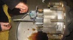
A manually adjusted hub assembly uses tapered roller bearings that require adjustment by the technician when the hub is installed on to the vehicle. TMC Recommended Practice (RP) 618 provides a good work instruction for manual bearing adjustment. Manual bearing adjustment must include the use of a dial indicator to insure that the bearings are adjusted to have from 0.001- to 0.005-inch of end play.
Like hubs with manually adjusted wheel bearings, PreSet and LMS hub assemblies use tapered roller bearings. While these bearings function like the bearings used in manually adjusted wheel ends, they are what the industry refers to as “half stand” bearings. They are manufactured to a closer tolerance than the bearings used in manually adjusted bearing systems.
When coupled with a hub that has the bearing cup seat-to-seat distance closely controlled, and the addition of a precision machined bearing spacer, PreSet or LMS hubs do not require that the bearings be manually adjusted. By design, the components work together to provide the proper wheel bearing end play without requiring that the technician manually adjust the bearings. Each hub assembly is tested at the factory to insure that when the hub is installed onto the spindle and the spindle nut is tightened to the proper torque, the bearing end play will be in the optimum operating range.
Unitized hub assemblies use a special cartridge type tapered roller bearing system. They are assembled, lubricated and sealed at the factory. They are installed on to the spindle as a sealed, pre-lubricated unit. When the spindle nut is torqued to the proper torque range, no further adjustment is required. Several of the unitized hub assemblies have a unique hub cap that aids in the identification of the wheel end.
INSPECTION
Regardless of the wheel end type, they all must be inspected on a regularly scheduled basis. TMC RP 631A lists four levels of recommended inspection. Most wheel end manufacturers also list similar inspection requirements.
The most frequent inspection is the driver pre-trip/in-service inspection. It includes a walkaround inspection where the driver should look for signs of leaks at the hub cap or the wheel seal, or lubricant soaked brake linings. The driver also should look for broken, loose or missing components. If the hub cap has a sight glass, the level and condition of the lubricant needs to be verified.
At each scheduled preventive maintenance inspection, all of the things previously listed should be checked. In addition, the wheels of the vehicle should be lifted and supported, and each wheel s rotated and checked for signs of quiet, smooth operation. Each wheel end should also be checked for signs of excessive end play.
Annually, each wheel end should be re-inspected as just outlined. In addition to these inspections, the hub cap or drive axle should be removed and the wheel bearing end play should be checked with a dial indicator.
If anything of concern is found at any level of inspection, wheel ends with manually adjusted or PreSet/LMS bearing systems should be completely disassembled for inspection. All individual components should be cleaned and inspected when the wheel end is disassembled.
Most manufacturers recommend that the wheel end be disassembled and inspected at 5 years/500,000 miles, or in conjunction with the second brake job. All components should be cleaned and inspected and replaced as necessary.
The exception to this is unitized hub assemblies. Unitized hub assemblies are not serviceable in the field, but should be regularly inspected per the manufacturer’s instructions. If anything of concern is found, the hub should be replaced.
SEALS
Sealing technology has improved with new materials and designs. Differences between seal manufacturers’ materials and designs make it mandatory that the instructions included with the seal be closely followed for proper installation. The seal should be replaced anytime the hub is removed from the spindle.
There are a variety of commercially available tools to aid in removing the seal from the hub. These tools insert between the seal and the bearing, and are used to pry the seal from the seal bore in the hub.
Never drive the bearing from the inside of the hub to push the seal from the seal bore. Damage to the bearing could occur that may be difficult to detect.
Some types of seals may separate when the hub is removed from the spindle. Use caution to prevent damage to the seal journal on the spindle when the inner portion of the seal is removed from the spindle. After the inner portion of the seal is removed, it may be necessary to use emery cloth to remove corrosion or foreign material from the seal journal on the spindle.
If the old seal is to be returned to the manufacturer for warranty consideration, efforts should be made to reduce damage to the seal from removal. Typically, the seal should not be cleaned before it is returned.
Do not use identification tags attached to the seal by a wire for identification purposes. The wire could damage the seal surfaces making it difficult to determine the failure mode. It is better to place the seal in a plastic bag as is after it has been removed from the vehicle. Mark the bag with the proper identification information.
Installation instructions included with the seal will identify if any surfaces of the seal should be lubricated prior to being installed. The instructions will also identify if special installation tools are needed, along with how they are to be used.
After the seal is installed, caution should be exercised to insure that the seal is not cocked or damaged as the hub is placed on to the spindle. As soon as the hub has been placed on the spindle, it should be supported and the outer bearing should be installed to prevent the seal from becoming cocked.
All seal manufacturers have an approved lubricants list. These lubricants have been tested with their seals to insure there will be no chemical reactions between the seal and the lubricant that would reduce the life of the seal. Only approved lubricants should be used in any wheel end.
In addition to the installation information that comes with the seal, most seal manufactures have product handbooks available that will provide additional information, including information on failure evaluation. While seal leaks are typically the most common type of wheel end maintenance, many seal performance issues can be prevented with the use of the proper installation tools, proper bearing adjustment, and handling procedures.
BEARINGS
Hubs with manually adjusted bearings and PreSet/LMS hub assemblies use tapered roller bearings and are serviceable. Unitized hub assemblies use a cartridge type tapered roller bearing assembly that can not be serviced.
The bearing cones should be washed in petroleum-based solvent prior to inspection. Once the bearings have been cleaned, blow compressed air through the rollers to dry the bearing. Do not spin the bearing with compressed air. The bearing could come apart causing damage or personal injury.
After the bearings have been inspected, if they are suitable to be reused, lubricate them in the same type of lubricant that will be used in the wheel end and store them in oil paper or a clean shop towel until you are ready to reassemble the hub.
Any bearing cup that shows signs of wear or damage should be replaced. If a bearing cone is dropped, it should be replaced. Damage from the impact could have occurred that may not be readily visible but could affect the operation of the bearing.
If the bearings are to be replaced, it will be necessary to remove the bearing cups from the hub. The bearing cups can be pressed out of an iron hub using a press or soft steel punch and a hammer. The bearing bores in an aluminum hub can be damaged if the bearing cups are driven out of the hub with a press or a punch.
To eliminate the chance of damage to the hub, weld a bead around the face of the bearing cup. Turn the hub over and allow the weld to cool.
As the weld cools, the bearing cup will shrink and will often slide out of the bearing bore. After the weld has cooled, if necessary, use a soft steel punch and a hammer to remove the cup from the bearing bore.
Once the bearing cups have been removed from the hub, clean the hub to remove old lubricant or foreign material that may be present. Once the hub is cleaned, inspect it for damage and then inspect the bearing and seal bores for signs of nicks, gouges or scratches. Use emery cloth to remove any surface imperfections that may be in the bearing or seal bores, or on the bearing cup seat. If the bores are scored or damaged, the hub should be replaced.
To install the new bearing cup in an iron hub, use the appropriate driver to prevent damage to the bearing cup. Verify the cup is pressed against bearing cup seat of the bore by using a 0.002-inch feeler gage to insure the cup is seated correctly.
To prevent damage to the bearing bore when installing the bearing cup in an aluminum hub, the hub should be heated using boiling water or an oven. Never attempt to heat the hub with a torch.
The bearing cup may also be chilled to aid in assembly. Heat the hub to 212 °F to 300 °F. Higher temperatures will make installation easier, but exceeding 300 °F will weaken the hub by destroying the heat treatment applied at time of manufacturing. Use the appropriate cup drive as necessary to seat the bearing cup. Once again, verify that the cup is pressed against the bearing cup seat of bore by using a 0.002-inch feeler gage to insure the cup is seated correctly.
Bearing manufactures have service information available that provides detailed cup removal and installation directions, procedures for bearing adjustment and failure analysis information. Bearing life can be greatly improved by following recommended procedures for installation and inspection.
SPINDLE NUT SYSTEMS
Probably the most commonly used spindle nut system is still the double jam nut system. It is currently used on both manually adjusted and PreSet or LMS hub assemblies.
Single spindle nut systems like the Axilok or ProTorq spindle nuts are becoming more common. While the single nut systems were designed to be used for manually adjusted bearing systems, they may also be used on PreSet and LMS hub systems.
There is a significant difference in the assembly procedures for manually adjusted and PreSet or LMS bearing systems, as well as between the various spindle nut systems. This is one of the key areas where the wheel end must be correctly identified and installed per the proper instructions.
Unitized hub assemblies typically have unique spindle nut systems and assembly torque requirements that are much higher than the assembly torque for manually adjusted and PreSet or LMS hub assemblies. It is important that the correct assembly procedure be followed for proper installation of unitized hub assemblies.
LUBRICATION
Lubricants currently used in wheel ends vary from CD 50 oil up to NLGI 1, 2 and 3 greases. While PreSet and LMS hub assemblies should not be lubricated with NLGI 1, 2 or 3 greases, most unitized hub assemblies are lubricated at the factory with Grade 2 synthetic grease.
Many fleets now specify NLGI grade 00 semi-fluid grease in trailer hubs. Trailer hub manufacturers have responded and added lubricant fill plugs to the barrel of the hub to aid in installing the lubricant.
The fill volume for semi-fluid grease in trailer hubs is critical. The use of a metered dispenser is advised to insure the recommended amount of grease is installed. Installation procedures for manually adjusted hubs are described in TMC RP 631A.
CONCLUSION
In recent years, changes in wheel bearing systems, spindle nuts systems, seals and lubricants have made it mandatory that product specific service information is referenced prior to servicing wheel end components. While most of the changes have made it easier to service a wheel end, there are some specific requirements for each system that need to be identified and followed closely to insure safe operation of the vehicle.
Manufacturers have responded by making service information available in a variety of formats, including installation instructions included with the product, service manuals and online service information and training accessible through the Internet. Take advantage of the resources available and RTB (read the book) before you begin any wheel end service.
If you have any questions about a particular wheel end service requirement, contact the customer service group for the component in question for additional product support.


