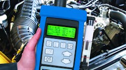
Vehicle Application: 2005 Chevrolet Express 2500 4.8
Customer Concern: Trouble codes P0171 and P0174. The vehicle does not go over 60 MPH under heavy throttle but will accelerate with less throttle.
Average Reported Mileage: 11013
Tests/Procedures:
1. Scan test the Powertrain Control Module (PCM) engine load to be above 80 percent under heavy engine loads. If low, clean the Mass Air Flow (MAF) sensor and retest.
2. If the engine load is high, check the injector pulse to be high under heavy engine loads.
3. If OK, check for a fuel delivery problem, install a fuel pressure gauge, start the engine and bleed any air/take fuel sample by opening the valve (depress the button) on the fuel pressure gauge and the engine should maintain idle and fuel volume should exceed 1 pint in 30 seconds.
4. If the engine stalls during the test, replace the fuel filter and/or fuel pump.
Tools used for this article:
- Scan tool
- Oscilloscope
- MAF cleaning chemicals
- Fuel injection tester
Data and DTCs
The Diagnostic Trouble Codes (DTCs) indicate lean air/fuel ratio on both banks. It’s important to remember that air/fuel ratio is a calculation, not a direct measurement. It’s based on data from several sensors, including the Mass Air Flow (MAF) sensor. In Step 1, a scan tool is used to check the data reported by the MAF sensor.
Scan tools communicate with the Powertrain Control Module (PCM), so sensor data shown in scan tool Mode 1 (live data) is not an actual sensor signal, it’s what the PCM interprets the signal to mean. When a sensor malfunctions, the PCM makes the decision to turn on the Malfunction Indicator Light (MIL) and set a DTC. But a MAF sensor can ‘fail within spec,’ meaning it still works well enough that the PCM won’t detect anything wrong, but it’s no longer accurate, and the PCM cannot detect inaccuracy. However, you can check its accuracy by reading Engine Load on a scan tool.
Looking at the data stream or Parameter IDs (PIDs) in Mode 1, Load should increase dramatically under full-throttle acceleration (this test requires two people or a scan tool with a recording or ‘movie’ mode). Load is also a calculated number, using data from the MAF sensor and the Manifold Absolute Pressure (MAP) sensor. If there’s no MAP sensor code and Load doesn’t reach at least 80% under full throttle, the MAF sensor needs closer attention.
Spray products can be used to clean a MAF sensor, but it’s unlikely you’ll get it clean enough to regain its calibration. But before buying a new sensor, many techs will clean a MAF sensor anyway just to see if that makes a difference.
Injector Pulse
Step 2 calls for checking fuel injector pulse or ‘pulse width,’ the amount of time the injectors are turned on. The amount of fuel being injected depends on pulse width and fuel system pressure. In this particular case, Steps 2 and 3 could be interchanged, but both are needed for a complete diagnosis.
The best way to check injector pulse width is with an oscilloscope, and there are two ways to view that signal; current and voltage. Acquiring the current signal requires a low-amp current probe, while a voltage signal can be acquired by back-probing the injector connector. Each signal by itself provides useful information, but both are needed for a complete picture. A current waveform provides more information about the injector itself, while a voltage waveform shows what’s happening in the control circuit. Here we’re looking a PCM pulse width command, so we want a voltage signal.
At rest, both sides of the injector circuit are high (battery voltage). When the PCM activates a driver, one side of the circuit drops to ground, allowing current to flow. From that point until several milliseconds after the end of the injection event, the scope trace presents a lot of information about the injector and its control circuit. Does circuit voltage go all the way to ground or does it ‘float’ slightly above zero volts? Does voltage stay down when the circuit is active or does it gradually rise? Is there a tell-tale ‘hump’ in voltage as the injector begins to open? Does injector pulse width increase with load? When the circuit is turned off, how high is the ‘fly-back’ voltage and how long does it last?
The answers to these and several other questions present a detailed picture of what’s happening in the injector circuit. With an oscilloscope you can examine the injector, the PCM driver, the circuit between them and many other details about what the PCM and engine are doing. With training, knowledge and experience, this can be one of most powerful and versatile diagnostic tools in your shop. In this case, we want to see if injector pulse width continues to increase as load increases.
Fuel Delivery
Low fuel pressure will make an engine run lean at all loads, while low fuel flow will prevent the engine from making power at high loads. On most GM engines, it’s easy to check pressure and quantity at the Fuel Pressure Service Connection on the fuel rail.
By activating the fuel pump with a scan tool, or by replacing the fuel pump relay with a test switch, the pump can be run without running the engine. Once the pressure gauge is connected, an accurate reading depends on bleeding air from the gauge and fuel rail, because air will is compress. Fuel quantity is measured by flowing fuel from the Service Connection on the fuel rail into a calibrated container. A fuel injection test kit includes all the necessary fittings and hoses for all of these tests.
On this particular vehicle, a new MAF sensor fixed the problem. Some techs would also check for high exhaust backpressure with a gauge in the oxygen sensor mounting hole. The point is, no matter what codes or symptoms are presented, it takes more than one test to arrive at an accurate diagnosis.


